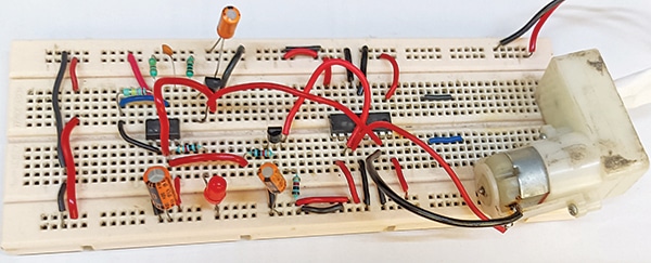
The combination of a 555 timer and L293D motor driver in an computerized wiper management gadget presents a sensible and environment friendly resolution for enhancing driver security and comfort. This technique, with its simplicity and cost-effectiveness, is usually a precious addition to each three- and four-wheelers. Fig. 1 reveals the writer’s prototype on a breadboard.

Circuit and dealing
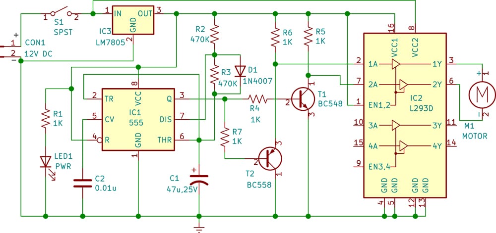
The circuit diagram of the automated wiper management for 3/four-wheelers is proven in Fig. 2. It’s constructed round a 12V battery, timer 555 (IC1), motor driver L293D (IC2), 5V voltage regulator 7805 (IC3), and some different parts. LED1 acts as a power-on indicator when swap S1 is turned on, activating the wiper management system.

| L293D pin logic for motor course | |||||
| Pin1 (EN1,2) | Pin2 (1A) | Pin7 (2A) | Pin3 (1Y) | Pin6 (2Y) | Motor Rotation |
| H | H | L | H | L | Clockwise |
| H | L | H | L | H | Anti clockwise |
The center of the gadget is the 555 and L293D. The 555 timer (IC1) is a extremely secure built-in circuit used for producing exact time delays or oscillation. It’s wired as an astable multivibrator. In a standard astable multivibrator circuit, an obligation cycle of fifty% or much less can’t be generated. To realize an obligation cycle of lower than 50%, diode D1 is added throughout resistor R3, leading to an output frequency of roughly 0.03Hz. The output of IC1 is given to transistors T1 and T2 to supply pulses, that are used because the inputs of IC2 to drive the L293D.
The L293D is a quadruple high-current half-H driver designed to supply bidirectional drive currents of as much as 600mA at voltages from 4.5V to 36V. It’s very best for controlling the wiper motor, permitting for ahead and reverse movement important for wiper operation.
| Elements Checklist |
| Semiconductors: IC1 – 555 timer IC2 – L293D motor driver IC3 – LM7805, 5V voltage regulator T1 – BC548 npn transistor T2 – BC558 pnp transistor D1 -1N4007 rectifier diode LED1 – 5mm LED (inexperienced/crimson) Resistors (all 1/4-watt, ±5% carbon): Capacitors: Miscellaneous: |
The output pin 3 of IC1 is linked to at least one finish of two resistors, R4 and R7. The opposite finish of resistor R4 is linked to the bottom of the NPN transistor T1 to supply a sign at pin 7 of the L293D, whereas the opposite finish of resistor R7 is linked to the bottom of the PNP transistor T2 to supply a sign at pin 2 of the L293D.
Usually, when there isn’t any rain, swap S1 needs to be off to disable the circuit, protecting the wiper motor inactive. When rain begins, swap S1 on to activate the circuit and provoke the wiper motor’s rotation to wash droplets from the automobile’s windscreen.
The wiper rotates clockwise and anticlockwise based mostly on the sign acquired at pins 2 and seven of the L293D. These alerts are offered by the output of timer 555 (IC1) by transistors T1 and T2. The L293D output is linked to a geared motor to which the wiper is fitted. Allow pin 1 is linked to a excessive voltage of 5V (logic 1) to allow the driving force. The wiper motor receives energy and management alerts to function the wipers.
The L293D has 16 pins in whole, as follows:
Pin 1 is Allow 1, which activates/off the primary H-bridge. Pin 2 is enter 1 (1A), which is the primary enter for motor 1. It’s linked to the emitter of the PNP transistor T2. Pin 3 is output 1 (1Y) for motor 1. Pins 4 and 5 are grounded. Pin 6 is output 2 (2Y) for motor 1. Pin 7 is enter 2 (2A), which is the second enter for motor 1. Pin 8 is linked to 12V to energy the wiper motor.
These first eight pins of the L293D are used to regulate the primary DC geared motor to rotate the wiper.
Equally, there are two inputs and two outputs to regulate the second DC motor, although it’s not used right here. For extra particulars, check with the datasheet. See the desk on earlier web page for the course of motor rotation.
Building and testing
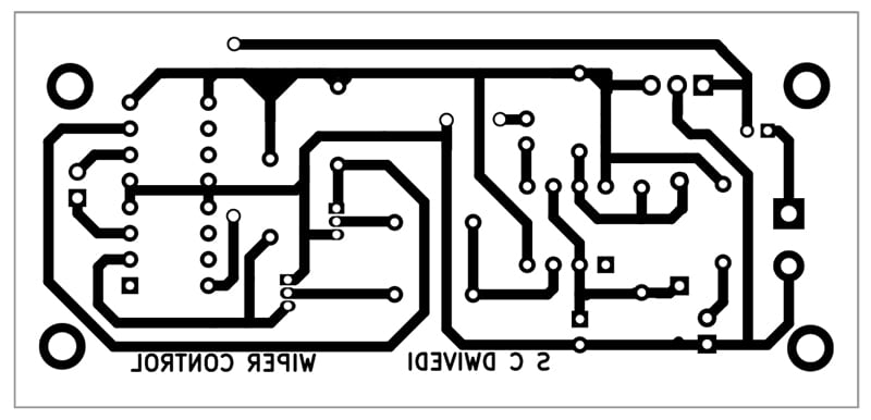
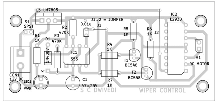
An actual-size, single-sided PCB structure for the automated wiper management for 3/four-wheelers is proven in Fig. 3, and its element structure in Fig. 4. After assembling the circuit on the PCB, enclose it in an appropriate field. Repair LED1 and CON1 on the entrance facet of the field. Change S1 must also be mounted on the entrance facet of the field for handy on/off management of the circuit. LED1 ought to glow when S1 is turned on after connecting a 12V battery or adaptor throughout CON1 to allow the circuit.


After assembling the circuit, enclose it in an appropriate field and set up the wiper on the motor shaft. Place the wiper to cowl the utmost glass space when rotating. The automated wiper management for 3/four-wheelers is now prepared to be used.
Bonus. You’ll be able to watch the video of the tutorial of this DIY challenge at https://www.electronicsforu.com/videos-slideshows/live-diy-automatic-wiper-control-for-three-four-wheeler
S.C. Dwivedi is an electronics fanatic and circuit designer at EFY
👇Comply with extra 👇
👉 bdphone.com
👉 ultraactivation.com
👉 trainingreferral.com
👉 shaplafood.com
👉 bangladeshi.assist
👉 www.forexdhaka.com
👉 uncommunication.com
👉 ultra-sim.com
👉 forexdhaka.com
👉 ultrafxfund.com
👉 ultractivation.com
👉 bdphoneonline.com


