


We construct this Arduino-based Digital Thermometer for temperature measurement functions.
Thermometers have been helpful for temperature measurement for a very long time. A digital thermometer is an digital machine used for correct temperature measurement. In contrast to conventional analog thermometers, which use mercury or different liquids, digital thermometers make the most of digital sensors to detect and show temperature readings.
Digital thermometers are generally employed in healthcare settings for monitoring physique temperature. They’re additionally precious within the meals business to make sure correct cooking and storage temperatures. Moreover, they’re utilized in environmental monitoring to measure ambient temperatures in varied settings.
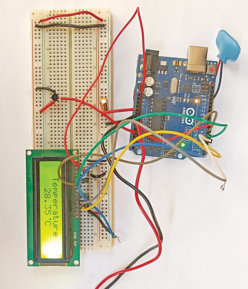
Digital thermometers provide comfort, accuracy, and ease of use, making them a well-liked alternative for a variety of temperature measurement functions. The creator’s prototype of an Arduino-based digital thermometer on a breadboard is proven in Fig. 1.
| PART LIST for Digital Thermometer | |
| Semiconductors: | |
| IC1 | – LM35 temperature sensor |
| Resistors (all 1/4-watt, ±5% carbon): | |
| R1 | -1-kilo-ohm |
| R2 | -220-ohm |
| Capacitors: | |
| C1 | -4.7μF, 25V electrolytic |
| Miscellaneous: | |
| BOARD1 | -Arduino Uno board |
| LCD1 | –16×2 LCD show |
| CON1 | -2-pin connector |
| -Jumper wires (15 no.) | |
| -9V battery/9V adaptor | |
Arduino-based Digital Thermometer – Circuit and Working
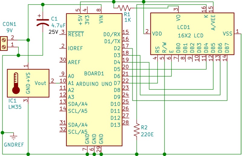
The circuit diagram of the thermometer is proven in Fig. 2. The thermometer is constructed round an Arduino board (BOARD1), a temperature sensor LM35 (IC1), a 16×2 LCD (LCD1), and some different elements. Merely join a 9-volt battery or adaptor to the board to function it.

The LM35 is an analog temperature sensor that outputs a voltage proportional to the temperature. The Arduino processes this data to show the temperature on the LCD.
The LM35 temperature sensor is used to sense the atmosphere’s temperature, producing a sign that signifies a 1-degree temperature change for each 10mV change at its output pin. For instance, if the output voltage of the LM35 sensor is 250mV, it means the temperature is round 25 levels Celsius.
Arduino reads this output voltage of the temperature sensor utilizing Analogue pin A1 and performs calculations to transform this analog worth to a digital worth representing the present temperature. After these calculations, the Arduino Uno sends the temperature sign to the 16×2 LCD utilizing applicable instructions.

On this thermometer, the Arduino is used to manage your complete system. Arduino is an open-source {hardware} platform for growth functions that runs on an ATmega controller.
Additionally Verify: Attention-grabbing DIY Arduino Tasks
The 16×2 LCD is extensively utilized in embedded techniques as a result of it’s low-cost, available, small in measurement, and straightforward to interface. It consists of two rows and 16 columns, that means it has 16 blocks of 5×8 dots. It requires 16 pins for connections, together with 8 information bits (D0-D7) and three management bits (RS, R/W, and EN). The remaining pins are used for provide, brightness management, and backlight.
Arduino Code for Digital Thermometer
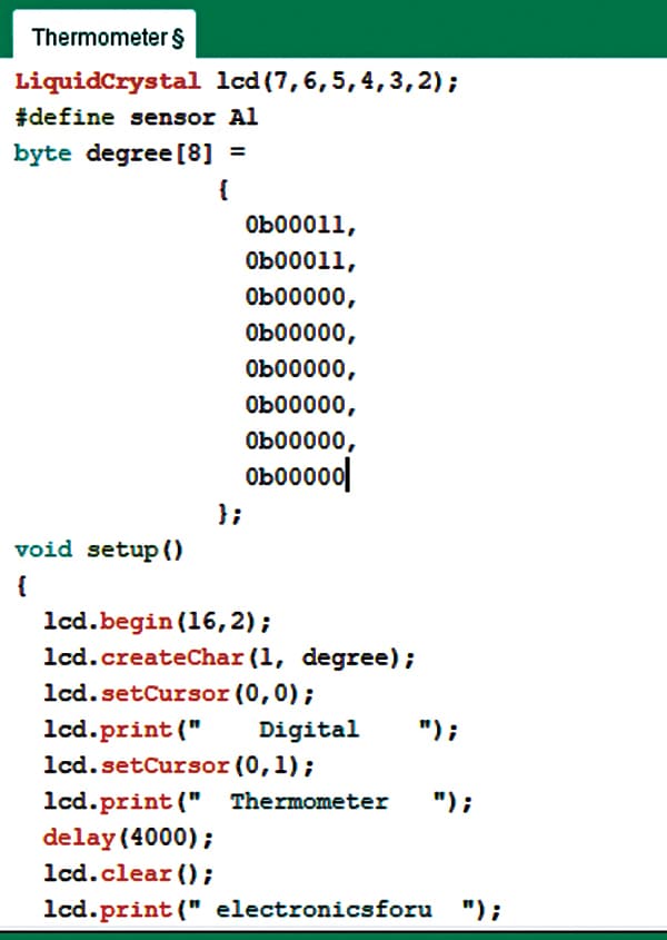
The code for temperature measurement utilizing LM35 is described right here. A library for the LCD unit is included after which information and management pins for the LCD and temperature sensor are outlined. After acquiring an analog worth on the analog pin, that worth is learn utilizing the Analogue learn operate and saved in a variable. Then, the worth is transformed into temperature by making use of the related components. A snippet of the supply code is given in Fig. 3.
Development and Testing
First, add the supply code into the Arduino Uno board after choosing the board and port.
Then, assemble the circuit on a breadboard. Make the connections fastidiously as proven within the schematic in Fig. 2. The 16×2 LCD unit is instantly linked to the Arduino Uno board in 4-bit mode. Knowledge pins of the LCD, specifically RS, EN, D4, D5, D6, D7, are linked to Arduino digital pins D7, D6, D5, D4, D3, D2.
The output of the temperature sensor LM35 is linked to Analogue pin A1 of the Arduino Uno, which generates 1 diploma Celsius temperature for each 10mV output change at its output pin. The 9V battery or 9V adaptor is linked to the Arduino Uno board. The digital thermometer is able to use.
Bonus: You possibly can watch the video of the tutorial of this DIY challenge beneath:
Verify different Digital Thermometer Tasks
S.C. Dwivedi is an electronics fanatic and circuit designer at EFY