


Lidar performs a key position in cartography, mapping, localisation, ADAS, atmosphere scanning, and extra. It’s extensively utilized in robots, autonomous automobiles, and for intruder monitoring. Nonetheless, many methods are wired, making them cumbersome for prototyping and testing, significantly in autonomous driving, the place mounting and connecting a lidar could be troublesome.
Right here, we current a Wi-Fi-enabled standalone lidar that scans and delivers real-time knowledge wirelessly. Merely join it to a battery, and it is able to use—no wiring required.
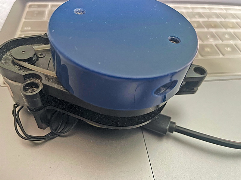
This machine allows versatile lidar deployment for mapping, monitoring, and comparable duties. We mixed the IndusBoard with a lidar unit to scan environment, generate knowledge, and create real-time wi-fi maps displayed on an internet web page. Fig. 1 exhibits the IndusBoard mounted to the lidar. The elements for the venture are listed in Desk 1. Fig. 2 exhibits the lidar used throughout testing.


| Desk 1 Invoice Of Supplies | ||
| Elements | Description | Amount |
| IndusBoard | 3cm sized improvement board | 1 |
| 360 diploma lidar | YD X2 lidar | 1 |
| 5V battery | Energy supply | 1 |
| 3.3V voltage regulator | DC-DC 5V to three.3V regulator | 1 |
You’ll be able to choose any lidar mannequin; on this venture, we used the YD X2 lidar. In line with the datasheet, it could actually scan 360 levels and measure as much as 8 metres, however different lidars can measure as much as 1km. Select primarily based in your necessities.
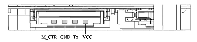
Let’s assessment the lidar datasheet. The YD X2 lidar supplies rotation angle and distance knowledge through serial peripherals at a baud charge of 115200. It features a connector board for USB connection to a PC (see Fig. 3 and Desk 2).

| Desk 2 Pin mapping | |||||
| Pin | Sort | Description | Defults | Vary | Remarks |
| VCC | Energy provide | Constructive | 5V | 4.8V-5.2V | / |
| Tx | Output | System serial port output | / | / | Knowledge stream: Lidar to peripherals |
| GND | Energy provide | Unfavorable | 0V | 0V | / |
| M_CTR | Enter | Motor pace management terminal | 1.8V | 0V-3.3V | Voltage pace regulation or PWM pace regulation |
As proven in Desk 3, the lidar senses distances from 0.12 to eight metres, scanning 360 levels at 3000Hz. With this knowledge, we will now join the lidar to the IndusBoard. You’ll be able to energy each elements with a 5V battery or an adaptor. For a conveyable answer, use the battery; in any other case, the 5V adaptor works nicely. Fig. 3 exhibits the lidar connector pins.
| Desk 3 Lidar datasheet | |||||
| Merchandise | Min | Typical | Max | Unit | Remarks |
| Ranging frequency | / | 3000 | / | Hz | Ranging 3000 instances per second |
| Motor frequency | 5 | 6 | 8 | Hz | Want to hook up with PWM sign, really helpful to make use of the pace of 6Hz |
| Ranging distance | 0.12 | / | 8 | m | Indoor atmosphere with 80% reflectivity |
| Discipline of view | / | 0-360 | / | Deg | / |
| Systematic error | / | 2 | / | cm | Vary≤1m |
| Relative error | / | 3.5% | / | / | 1m<Vary≤6m |
| Tilt angle | 0.25 | 1 | 1.75 | Deg | / |
| Angle decision | 0.60 (frequency @5Hz) | 0.72 (frequency @6Hz) | 0.96 (frequency @8Hz) | Deg | Totally different motor frequency |
Circuit diagram
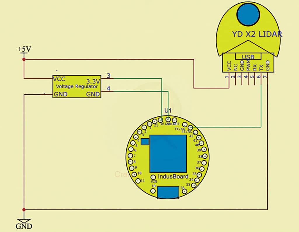
Fig. 4 exhibits the circuit diagram for the IndusBoard standalone IoT lidar radar. The machine is powered by a 5V battery, with the lidar managed through PWM indicators by the RX pin. Output is distributed to the serial port.
Software program
Relying on the lidar model, you should use the suitable Arduino library. Right here, a library appropriate with the YD X2 lidar to retrieve knowledge was utilised.
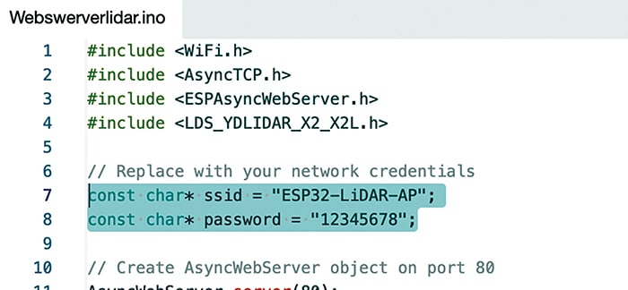
First, configure the Wi-Fi SSID and password within the code. You’ll be able to join the lidar to an present Wi-Fi community or set it as a Wi-Fi entry level (AP). On this venture, we set the lidar as an AP. Fig. 5 exhibits the code snippet for configuring the AP.
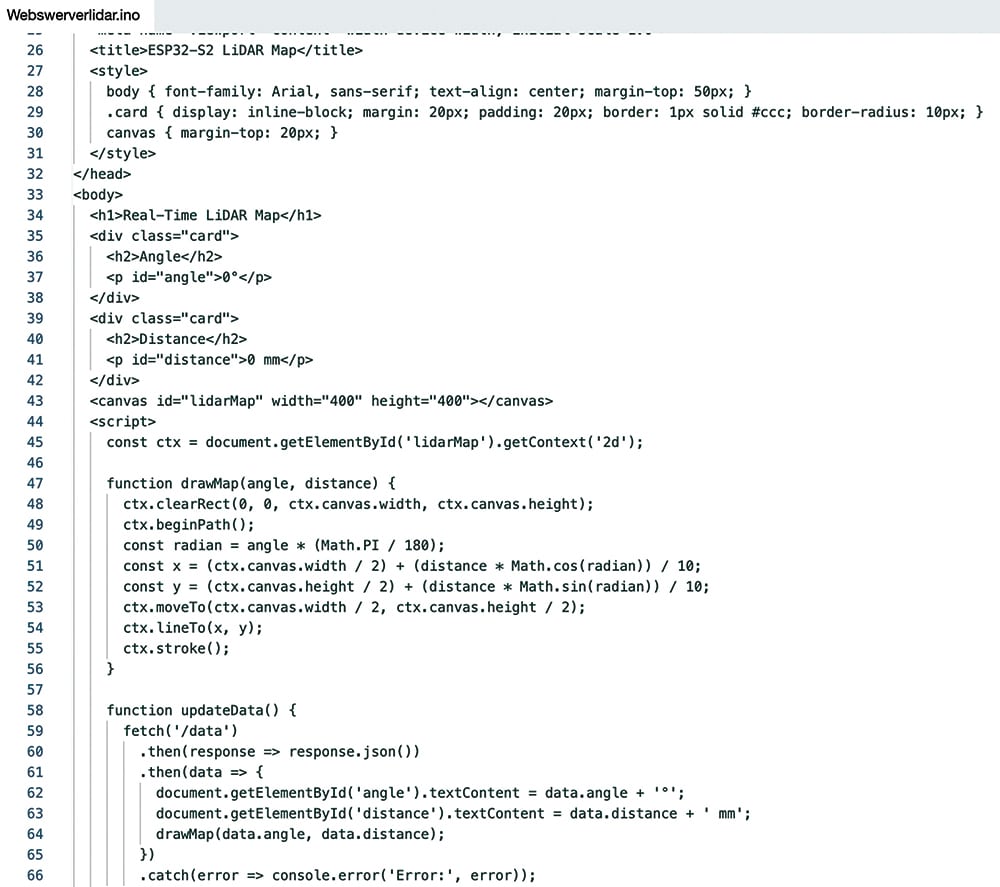
Subsequent, outline the serial pins, ports, and PWM motor management pin within the code. Write the online web page utilizing HTML, CSS, and JavaScript to show the map and knowledge in actual time over Wi-Fi. Fig. 6 exhibits the online web page’s code snippet.
Development and testing
After importing the supply code, full the wiring as per Fig. 4. Join the lidar motor management pin to any PWM-enabled pin on the IndusBoard. The serial knowledge pin may also be related to any pin, however on this case, RX pin 43 was used.
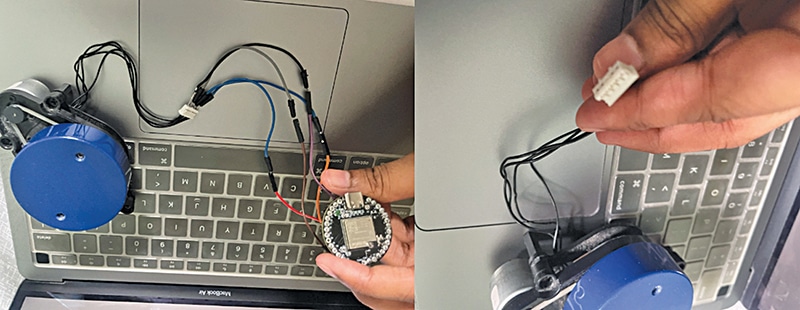
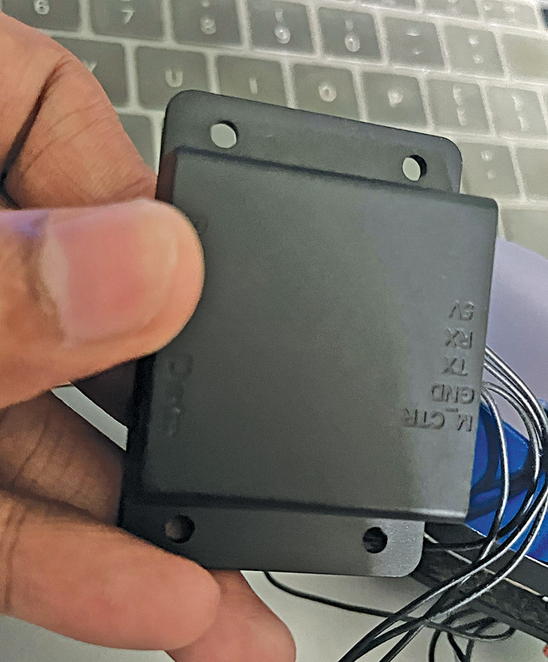
For testing, join the lidar’s connector both through a header pin or by soldering on to the board. Mount the IndusBoard and lidar as proven in Fig. 7. The IndusBoard, being sufficiently small, matches behind the lidar. Fig. 8 exhibits the lidar pin USB connector module, with pin numbers marked.
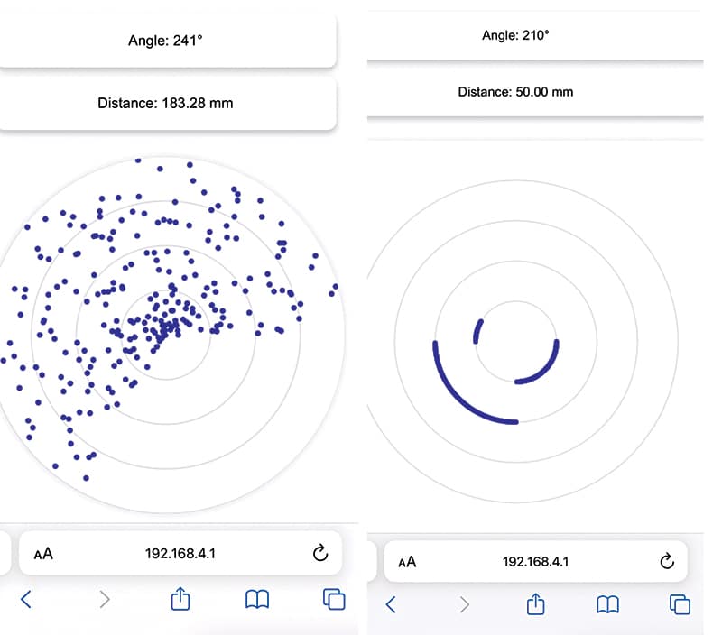
After meeting, energy on the lidar and set up a Wi-Fi connection. Open an internet browser and navigate to the IndusBoard’s default IP handle: 192.168.4.1. The online web page will show the real-time map and supply distance and angle knowledge. Fig. 9 exhibits the lidar scan knowledge plotted on the net web page.
Ashwini Kumar Sinha, an IoT and AI fanatic, is a tech journalist at EFY
👇Observe extra 👇
👉 bdphone.com
👉 ultraactivation.com
👉 trainingreferral.com
👉 shaplafood.com
👉 bangladeshi.assist
👉 www.forexdhaka.com
👉 uncommunication.com
👉 ultra-sim.com
👉 forexdhaka.com
👉 ultrafxfund.com
👉 ultractivation.com
👉 bdphoneonline.com