

Analysis and growth engineer Paul Bupe, Jr has revealed particulars on a brand new method to mushy robotic sensing, developed throughout his PhD analysis: OptiGap, which began with low-cost 3D printer filament and ended with a purposeful bend sensor providing bend-localization capabilities.
“In very normal phrases, this sensor is mainly a rope that if bent can let you know the place alongside its size you bent it. The flamboyant time period for that’s ‘bend localization,'” Bupe explains. “OptiGap’s utility is especially throughout the realm of sentimental robotics, which usually includes compliant (or ‘squishy’) techniques, the place using conventional sensors is usually not sensible. The title OptiGap, a fusion of ‘optical’ and ‘hole,’ displays its core precept of using air gaps inside versatile optical mild pipes to generate coded patterns important for bend localization.”
A size of 3D printer filament and a few silicon sleeves is sufficient to create a surprisingly intelligent bend sensor dubbed OptiGap. (📷: Paul Bupe, Jr.)
The concept of utilizing optical mild pipes as bend sensors is not new: one thing so simple as a size of fiber-optic cable with an LED at one finish and a photoresistor on the different can be utilized to get an thought of how a lot the sensor is bending, however what it may’t do is let you know the place. That is the place OptiGap is available in — and preliminary prototypes have been made utilizing a easy size of clear TPU filament designed to be used in 3D printers.
“To confirm [my] speculation, I hooked up an extended piece of TPU to a tape measure and commenced bending it at varied factors to look at how mild transmission would change,” Bupe explains, referring to a principle that the adhesive from electrical tape used to connect the 2 collectively was inflicting stretches within the filament and a drop within the quantity of sunshine transmitted because the filament bent.
Later revisions of the undertaking switched to skinny optical fibers, to cut back the scale of the sensor. (📷: Paul Bupe, Jr.)
“I wrote a small Linux I2C driver for the [STMicroelectronics] VL53L0X ToF [Time of Flight] sensor to run on a Raspberry Pi and push the info to a socket utilizing ZeroMQ,” Bupe continues. “I then created a tough GUI in Python to drag the sensor knowledge from the socket and visualize the sunshine transmission knowledge in realtime […] which in a short time validated my speculation. This validation marked the ‘Eureka!’ second that sparked the eventual growth of the OptiGap sensor.”
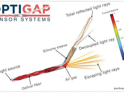
Bupe then moved to experimenting with air gaps, reducing the filament into shorter lengths and attaching them collectively utilizing mushy rubber sleeves. Because the sleeve bends, much less of the sunshine from one part of filament makes it to the subsequent. By putting the air gaps in a specific sample, impressed by the operation of a linear encoder, it is potential to determine the place alongside the sensor’s size the bend is going down.
The spacing of the gaps encodes info in such a manner as to have the ability to decide which phase is bending. (📹: Paul Bupe, Jr.)
Having confirmed OptiGap’s capabilities, Bupe switched from filament to significantly thinner PMMA optical fibers — and dropped the VL53L0X ToF sensor in favor of utilizing photodiodes and LEDs. “This additionally allowed me to make use of a microcontroller to learn the sensor knowledge,” Bupe notes, “which was a big enchancment over the preliminary prototype.” That microcontroller, an STMicro STM32, runs a naive Bayes classifier on-device to decode the encoded air-gap patterns and localize the bend.
Extra info on the undertaking is offered on Bupe’s web site, whereas his dissertation on the subject is offered on the College of Louisville’s Institutional Repository beneath open entry phrases.