


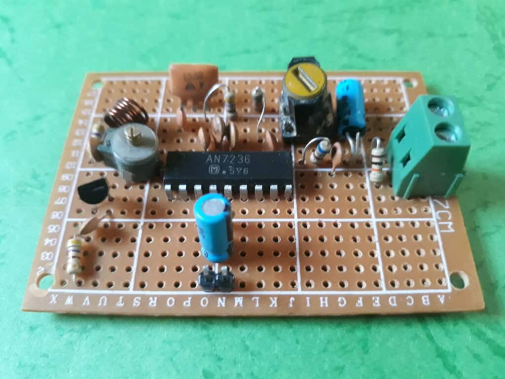
This can be a easy FM Radio Receiver which is construct round a single IC1 AN7236 (18-pin), a single HF transistor Q1( BF 494) and some exterior parts. This FM radio could be tuned for frequencies between 88.00MHz-108.00MHz. IC1 AN7236 is an 18-pinIC and this IC and different parts used on this FM radio could be bought simply in a market.
Circuit and dealing
The circuit may be very easy and easy. The guts of this circuit is a single IC1 AN7236. The circuit is split into the two components. The primary half is a RF part and the second half is a 5.5 MHz IF part. An HF transistor Q1 BF 494 was used within the first half and IC1 AN 7236 was used within the second half.

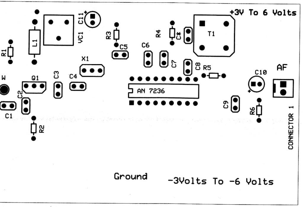
A transistor Q1 BF494, VC1 (2-22pF Trimmer Capacitor), ceramic capacitors C1, C2, C3, resistors (R1 and R2) and an inductor coil L1 (5 turns of 23 SWG wire 5mm air core) will work as an RF oscillator frequency between 93.5 MHz-113.5 MHz. Resistor R1 (470K) is related between +3V to +6Volts and a base of Q1 BF 494. Resistor R2 470) is related between emitter and floor. Inductor L1 and a trimmer capacitor VR1 are related in parallel to one another and to a provide +3V to +6V and a collector of Q1 (BF494). Capacitor C2 is related to provide +3 to +6 Volts and a base of Q1(BF494). A suggestions capacitor C3 was related between collector and emitter of Q1 BF 494. Trimmer capacitor VC1 works as Tuning between frequencies between 88.00MHz to 108.00MHz.
An antenna of 75cm will obtain the frequencies between 88.00MHz-108.00MHz. And, these frequencies are blended with the frequencies 93.5 MHz-113.5 MHz generated by oscillator frequencies contains HF transistors Q1 BF494 and different parts. An IF frequency of 5.5MHz generated after mixing is taken away from an emitter of Q1 BF494 to an enter of a 5.5 MHz ceramic filter by way of a ceramic capacitor C4 (47pF).
An IF frequency of 5.5MHz taken away fromC4 is handed to an enter of 5.5MHz ceramic filter is handed to a pin 16 of IC1 AN7236 by way of a capacitor C5 (.022uF). A resistor R3 (470) was related between pin-3 of X1 5.5MHz ceramic filter and floor.

Pin 12 is related to floor.Pin 14, 15 of AN 7236 is related to floor with a capacitor C6, C7 (.022uF). Pin 13 is related to +3Volts to +6 Volts.
A capacitor C11 (.01uF) and an electrolytic capacitor C12 (100uF/25V) have been related between +3Vand floor and can filters a DC voltage. Pin 11 is related to a T1 5.5 MHz IFT coil with a ceramic capacitor C8 and different terminals of T1 to the bottom. A resistor R4 (5K6) is related with parallel to T1 and floor. An audio output is taken away from a pin 10 by way of a resistor R5 (680) in sequence with an electrolytic capacitor C10 (1uF/25V) and to a 2-pin output connector. A resistor R6 (10K) is related between a destructive terminal of C10 (1uF/25V) and floor. A capacitor C9 (.003uF) is related between a optimistic terminal of C10 (1uF/25V) and to a floor which is able to filter an AF output sign.
Development and Testing
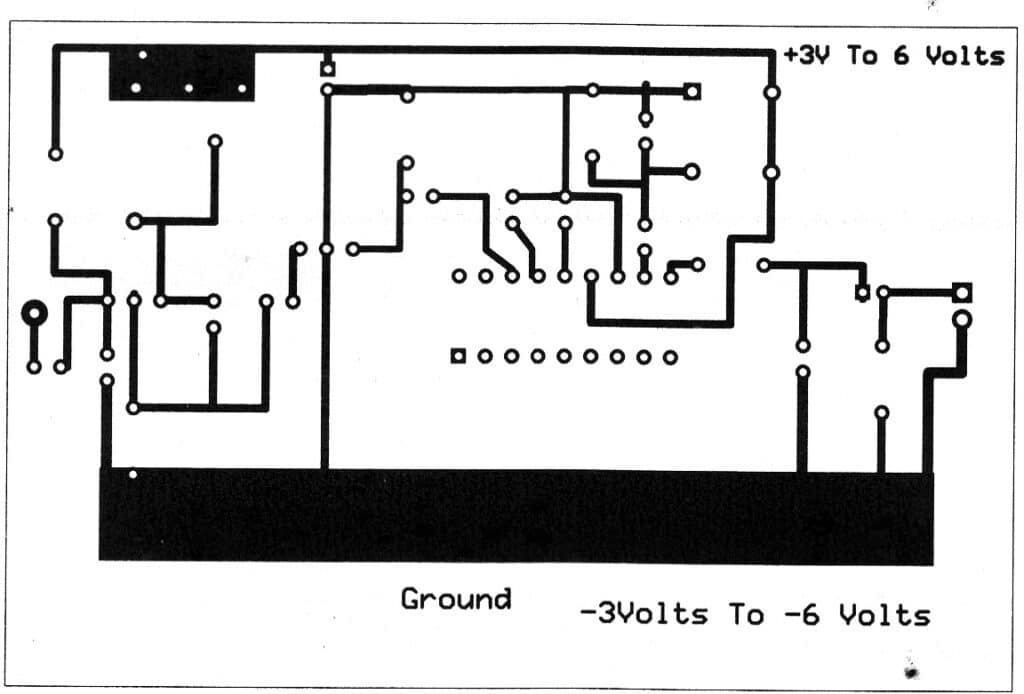
A vero-board of measurement 5cm*7cm is appropriate for making your FM radio. You might also construct your individual PCB whose PCB sample was given in an article. At first take an 18-pin IC socket and place it on a center a part of a veroboard (5cm*7cm). Place a 2-pin connector at a proper aspect of a veroboard. Now place all of the remaining parts like Q1 (BF494), VC1(2-22pF trimmenr capacitor), 5.5 MHz ceramic filter, 5.5 MHz IFT coil, resistors and ceramic capacitors e.t.c. as proven in a circuit diagram.

Now take a 15 Watt soldering iron and solder all of the parts. Don’t insert an IC throughout soldering in any other case it would injury an IC1.
Subsequent, we are going to make an inductor L1. For this you will have a bit of 23 SWG wire. Now wind a 5 flip of 23 SWG wire on 5 mm diameter of air core.
Join a bit of wire of 75cm lengthy wire to a base of a transistor Q1 BF 494 by way of a capacitor C1 (.001uF) if you’re getting low sign.
Now we are going to check a circuit. Take any AF amplifier and join it to an AF output terminal of your FM radio. Take a plastic screwdriver and gently tune a VC1 (Tuning capacitor) till you’ll hear a stations. Now tune a 5.5 MHz IFT core gently till you’ll hear clear audio output sound. Now your FM radio receiver is working and prepared for listening*
Observe: On this AN7236 FM radio we’re utilizing a 5.5MHz IF frequency within the state of 10.7MHz IF frequency as a result of 5.5MHz IFT coil (T1) and 5.5MHz ceramic could be simply discovered simply in a market and could be taken off out of your previous Black and White TV units and from different issues.
Elements Record
| Semiconductor | Q1: BF 494, IC1: AN 7236 |
| Resistors | R1: 470K |
| R2, R3: 470 | |
| R4: 5K6 | |
| R5: 680 | |
| R6:10K | |
| Capacitors | C1:0.001uF |
| C2, C11: .01uF | |
| C3: 10pF | |
| C4:47pF | |
| C5, C6 and C7:022uF | |
| C8:.001uF | |
| C9:.003uF | |
| C10: 1uF/25V | |
| X1: 3-pins 5.5MHz ceramic filter | |
| Miscellaneous | One 18-pins IC socket |
| One 2-pin connector | |
| 75 cm lengthy wire, vero board measurement 5cm*7cm, 3 V-6 V battery, 23 SWG copper wire, VC1: 2-22pF trimmer capacitor | |
👇Comply with extra 👇
👉 bdphone.com
👉 ultraactivation.com
👉 trainingreferral.com
👉 shaplafood.com
👉 bangladeshi.assist
👉 www.forexdhaka.com
👉 uncommunication.com
👉 ultra-sim.com
👉 forexdhaka.com
👉 ultrafxfund.com
👉 ultractivation.com
👉 bdphoneonline.com