


The bottom setup for this technique is situated in a room with approximate dimensions of 9.29 sq. metre. The room is non-air conditioned and doesn’t obtain any direct daylight. The proposed setup goals to guage the feasibility of utilising an electrode-based E201 BNC pH measurement sensor for assessing the pH of the water earlier than and after the addition of liquid vitamins.

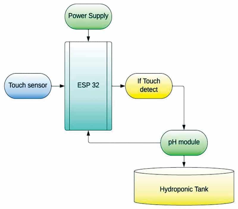
Fig. 1 illustrates the authors’ prototype showcasing varied points of the setup and its set up. Monitoring the pH worth is essential for sustaining optimum situations for plant development. The ESP32 is employed in deep sleep mode, and with the help of a contact sensor, the pH of the hydroponic answer could be measured with a easy contact. This contact sensor acts as an interrupt, triggering an exterior enter for the ESP32, thereby awakening it from deep sleep mode. Fig. 2 gives a block diagram illustration of your entire setup.
pH displays the hydrogen potential in an answer, offering a numerical worth that determines its acidity or alkalinity. The pH scale ranges from 0 to 14. A pH worth under 7 signifies acidity, whereas a price above 7 signifies alkalinity. pH serves as an important chemical indicator for hydroponic setups, reflecting adjustments in water because of the addition, absorption, and stability of liquid fertilisers. Frequent indicators akin to phenolphthalein, methyl purple, and bromothymol blue are utilised to point pH ranges of roughly 8 to 10, 4.5 to six, and 6 to 7.5, respectively.
Phenolphthalein transitions from colourless to pink, whereas methyl purple transitions from purple to yellow. This time period, broadly utilized in chemistry, biology, and agronomy, interprets the focus values of hydrogen ions, sometimes ranging between about 1 and 10–14 gram-equivalents per litre, right into a scale from 0 to 14.
The pH of an answer could be calculated by taking the destructive logarithm of the hydronium ion focus, expressed as pH= -log[H3O+]. At 25°C, an answer with pH<7 is acidic, pH>7 is primary, and pH=7 is impartial.

There are two strategies for measuring pH: colorimetric strategies utilising indicator options or papers, and extra correct electrochemical strategies utilizing electrodes and a millivoltmeter (pH meter). We’re using the latter methodology with the help of a microcontroller circuit for enhanced accuracy in readings.
Vegetation have various pH necessities; nonetheless, a pH vary of 5.5 to six.5 is usually thought-about optimum for hydroponic gardening. Most vegetation thrive in barely acidic situations. The generally used chemical substances to regulate pH are phosphoric acid (to decrease pH) and potassium hydroxide (to boost pH).
Whereas each chemical substances are comparatively protected, they will trigger burns and may by no means are available in contact with the eyes.

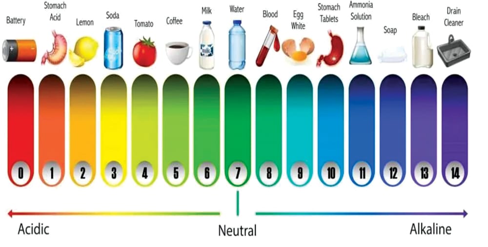
Particular vitamins necessitate sure pH ranges for optimum plant uptake. Incorrect pH ranges can result in deficiencies in sure vitamins or toxicity. As an example, when the pH degree drops under 5.0, vegetation could develop magnesium and calcium deficiencies, or copper and iron toxicity. Fig. 3 illustrates a typical pH scale and its correlation to on a regular basis objects in our lives.
ESP32 energy modes
Lively mode. On this mode, all peripherals of the chip stay lively, together with Wi-Fi, Bluetooth, and radio based mostly on program enter.
Modem-sleep mode. The CPU is operational, and the clock is configurable. The Wi-Fi/Bluetooth baseband and radio are disabled.
Mild-sleep mode. The CPU is paused, whereas the RTC reminiscence, RTC peripherals, and the ULP co-processor are operating. Wake-up occasions (MAC, SDIO host, RTC timer, or exterior interrupts) will awaken the chip.
Deep-sleep mode. Solely the RTC reminiscence and RTC peripherals are powered up. Wi-Fi and Bluetooth connection information are saved within the RTC reminiscence. The ULP coprocessor stays purposeful.
Hibernation mode. The inner 8MHz oscillator and ULP co-processor are disabled. The RTC restoration reminiscence is powered down. Just one RTC timer on the sluggish clock and particular RTC GPIOs are lively. The RTC timer or RTC GPIOs can get up the chip from hibernation mode.
The ESP32 deep sleep mode is utilised within the Arduino Cloud. Within the present setup, the ESP32 microcontroller is initialised into deep sleep mode and woke up as wanted. This may be achieved in 3 ways: timer get up, contact get up, and exterior get up.
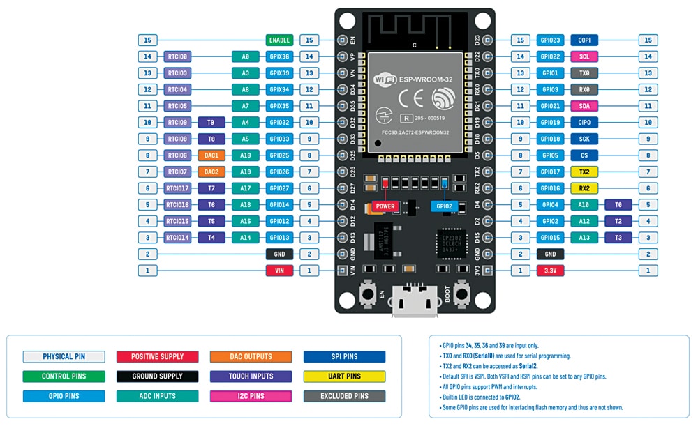
A comparability of the 5 totally different modes is supplied in Desk 1 from the ESP32 datasheet. The pinout is represented in Fig. 4, and Desk 1 shows the assorted energy modes and energy consumption of the ESP32 chip.
| Desk 1: Numerous energy modes of operation and energy consumption of ESP32 chip | ||||
| Energy Mode | Description | Energy Consumption | ||
| Lively (RF working) | Wi-Fi Tx packet | — | ||
| Wi-Fi/BT Tx packet | ||||
| Wi-Fi/BT Rx and listening | ||||
| Fashionable sleep | The CPU is powered up |
240MHz | Twin-core chip(s) | 30mA~68mA |
| Single-core chip(s) | NA | |||
| 160MHz | Twin-core chip(s) | 27mA~44mA | ||
| Single-core chip(s) | 27mA~34mA | |||
| Regular velocity: 80MHz | Twin-core chip(s) | 20mA~31mA | ||
| Single-core chip(s) | 20mA~25mA | |||
| Mild sleep | — | 0.8mA | ||
| Deep sleep | The ULP coprocessor is powered up | 150µA | ||
| ULP sensor-monitored sample | 100µA @ 1% obligation | |||
| RTC timer + RTC reminiscence | 10µA | |||
| Hibernation | RTC timer solely | 5µA | ||
| Energy off | CHIP_PU is ready to low degree, the chip is powered down | 1µA | ||
Timer get up, contact get up, and exterior get up
Each setup has distinctive necessities. On this setup, the pH of the water circulated within the hydroponics setup is monitored utilizing the E201 BNC. The ESP32 is maintained in deep sleep mode to preserve energy consumption. The microcontroller wakes up utilizing the exterior mode, which includes an hooked up contact sensor. Upon contact, the pH studying is taken, and the worth is displayed on the serial monitor.
Throughout deep sleep, among the ESP32 pins could be utilised by the ULP coprocessor, specifically, the RTC_GPIO pins and the contact pins. The ESP32 datasheet’s pinout identifies the RTC_GPIO pins, that are highlighted in a inexperienced rectangular field.
Exterior wakeup
Exterior wakeup is one other methodology of waking up the ESP32 board from deep sleep mode, the place a change in a GPIO pin’s state triggers the awakening. The wakeup supply should be configured earlier than setting the ESP32 board into deep sleep mode. Two varieties of exterior wakeups could be arrange: ext0 and ext1. Ext0 includes configuring one GPIO pin as an exterior wakeup, whereas ext1 is used for a number of GPIO pins. It is very important word that solely RTC GPIO pins can be utilized as a wakeup supply for exterior wakeup.
To allow the ext0 wakeup supply, use the next API:
esp_sleep_enable_ext0 wakeup()The RTC IO module is chargeable for triggering the ext0 wakeup. Because the RTC IO module is a part of the RTC peripherals energy area, the RTC peripherals should be powered on throughout deep sleep mode when utilizing ext0 as a wakeup supply.
Software program
The code is ready in Arduino IDE. Right here, the PIN is outlined for the sensor, after which the pH worth is extracted utilizing a components. Within the setup perform, the sensor information is processed with the sleep perform to allow the processor to sleep and wake on time to course of the sensor information. Fig. 5 reveals a snippet of the supply code.
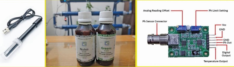
Fig. 6 represents further details about the setup and the elements used. The pinout of the sensing probe, together with the probe meeting, gives entry to the pH readings, considering the adjustment of offsets because of analogue readings and pH limits. Desk 2 shows the invoice of supplies, and Desk 3 reveals the pin connections for interfacing the sensor.
| Desk 2: Invoice of supplies | ||
| Parts | Quantity | Description |
| ESP32 (MOD2) | 1 | For programming |
| pH sensor (MOD3) | 1 | To sense the pH worth |
| Contact sensor (MOD1) | 1 | To provoke an exterior enter for taking readings |
| Jumper wires (male to feminine) | 3 | To attach the sensor |
| Desk 3 connections between mod1, mod2, and mod3 | |
| MOD3 (pH Sensor) | MOD2 (ESP32) |
| Voltage provide (5V) | Vcc (5V) |
| Output of sensor (A) | G35 |
| GND | GND |
| MOD1 (Contact Sensor) | MOD2 (ESP32) |
| Voltage provide (Vcc) | Vcc (5V) |
| Output of sensor (SIG) | G4 |
| GND | GND |

Circuit Diagram
The circuit is constructed across the contact sensor (MOD1), ESP32 (MOD2), pH sensor (MOD3), and some jumpers. Fig. 7 illustrates the wiring of the proposed setup on the breadboard, and Fig. 8 reveals the circuit diagram of the proposed system.
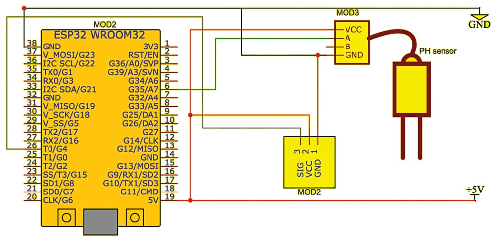
Earlier than assembling the mission, discuss with Fig. 7 and eight. After correct meeting of the circuit based mostly on the circuit diagram, add the code to ESP32 after which take a look at the gadget by powering it. You’ll obtain the pH worth within the serial monitor if you dip the sensor into the liquid to be measured.
Word. In conclusion, it’s doable to measure the pH of a hydroponic answer utilizing a sensor whereas conserving energy by working it in deep sleep mode.
Dr Geetali Saha is a school member on the Division of Electronics and Communication Engineering, GCET, Anand, Gujarat, and Dhruv Vachhani, a scholar coordinator from the third Yr CSE – IoT Division, is engaged on this sponsored mission with Dr Saha