
A DC motor is often operated by direct present. It converts {the electrical} vitality into mechanical vitality. This rotational motion is the supply of required energy to run many purposes in Business. Velocity management is the important perform for motor operation. With pace management of the motor, we are able to alter the pace of the motor in line with the will of the applying. It’s deployed in lots of real-time purposes like controlling robotic autos, paper mills, and elevators.
DC Motor
DC motor is a rotational system which converts electrical vitality within the type of Direct Present into mechanical vitality within the type of rotational movement of the motor shaft. The pace of the DC motor may be managed by various DC voltage. For making use of altering voltage, the PWM method is beneficial.
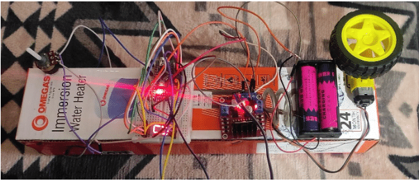
This circuit is constructed on a breadboard. This design is predicated on Arduino Nano Expertise. It includes Arduino Nano, L298 Motor Driver, Potentiometer 10K,1 Seven phase show, BO Motor 100 RPM, GearBox, Shaft, Battery Holder, Battery 18650 Li-on Cell 3.7V 2000mah(2 cell). The potentiometer has 3 pins – one is linked to GND, one is linked to 5V and the center pin is linked to A1(analog pin). The Seven phase pins a to g are linked from pin 13 to Pin 7 and the decimal pin is linked to six. This can be a frequent cathode 7-segment show with 2 frequent pins linked to GND. Pin 5 of Arduino Nano is linked to Allow Pin A of the L298 Motor Driver. The Pin 3 and Pin 4 are linked to IN1 and IN2 of the L298 Motor Driver. Connect BO Motors to motor pins of L298 Motor Driver and put wheels inside gearboxes. Motors may be managed by means of a potentiometer and pace is displayed on seven seven-segment show in RPM.
Arduino Nano
The Arduino Nano is a micro-size, full, and breadboard-compatible board based mostly on the ATmega328. The Arduino Nano may be powered through the Mini-B USB connection. The ability supply is mechanically chosen to the very best voltage supply. The ATmega328 has 32 KB. Every of the 14 digital pins on the Nano can be utilized as an enter or output, utilizing pinMode(), digitalWrite(), and digitalRead() capabilities. They function at 5 volts. Every pin can present or obtain a most of 40 mA and has an inside pull-up resistor.
L298 Driver
This L298N Based mostly Motor Driver Module – 2A is a high-power motor driver good for driving DC Motors and Stepper Motors. It makes use of the favored L298 motor driver IC and has the onboard 5V regulator which it could provide to an exterior circuit. It might probably management as much as 4 DC motors, or 2 DC motors with directional and pace management. This L298N Motor Driver Module – 2A is ideal for robotics and mechatronics initiatives and excellent for controlling motors from microcontrollers, switches, relays, and so forth. Excellent for driving DC and Stepper motors for micro mouse, line-following robots, robotic arms, and so forth.

10K Potentiometer
Potentiometers are useful in controlling the assorted electrical parameters of a circuit. This can be a one-turn 10k Potentiometer with a rotating knob facility. This potentiometer is used to vary the resistance between 0 to 10k ohms worth by merely rotating the knob. The shaft is 15mm in size with complete resistance of 10K ohm.
Seven Section Show
In trendy instances, seven-segment shows are generally utilized in show methods for varied purposes. Seven-segment shows are made up of LEDs. These are used to show numbers just like the standing of petrol in car, time in digital watches, show pace of autos, pace of washing machines, AC and varied kinds of panels. The Seven-segment show comprises 7 LEDs to show numbers. You’ll be able to show numbers from 0 to 9 on a single seven phase.
Frequent Cathode Seven-Section Show
- For the frequent cathode, join frequent pins of seven segments to GND pin of Arduino Nano.
- Join +5 volts pin of Arduino Nano to decimal level pin in sequence to a 470 ohm- resistor to restrict the present. It should glow.
- Within the Frequent cathode, a,b,c,d,e,f,g, and h pins of the phase show are linked to Arduino Nano pins which may be managed through programming by assigning worth
Components Checklist
- Arduino Nano
- L298 Driver
- BO Motor 100 RPM
- Frequent cathode Seven Section Show
- Potentiometer 10K
- Tyre
- Bread Board
- Jumper Wires
- USB Cable
- Cardboard Field
- Battery Holder
- Battery Module 18650 3.7V 2000mah (2 cell)
Software program
Programming of the challenge is finished on the Arduino 1.8.19 instrument. The Potentiometer 10k module is linked to the Arduino nano analog pin A1,1 pin is linked to 5V of Arduino Nano, 1 pin is linked to GND of Arduino nano. Pin 5 of Arduino Nano is linked to Allow Pin A of the L298 Motor Driver. Pin 3 and Pin 4 are linked to IN1 and IN2 of the L298 Motor Driver. Connect BO Motor 100 RPM to motor pins of L298 Motor Driver and put wheel inside gear field. By means of Software program, the Potentiometer sends analog sign to A1 pin and accordingly Arduino Nano sends the command to the L298 Motor Driver which in flip sends command to the Motor to run in line with the worth of the potentiometer.

Testing
Make connections as per the circuit diagram given. Give voltage from Battery Holder 18650 Li-on Cell 3.7 V 2000 mah(2 cell – 7.4V). Test the standing of seven-segment show if zero is displaying on it. Transfer the knob of the 10K potentiometer and document the pace displayed in RPM from 0 to 9 RPM . Right here 0 means 0 RPM and 9 means 90 RPM and single dot on seven-segment show means most pace is 100 RPM. Observe the pace of BO DC Motor in line with the rotation of the Knob(0-255).The Worth 0 from potentiometer means 0 RPM(revolution per minute-minimum pace), worth 255 refers – 100RPM (most pace). This prototype may be prolonged to 2 or extra motors with further seven-segment show or LCD show with path management of DC motor for varied robotics and industrial purposes.

Supply Code
int seg_Pins[] = {13, 12, 11, 10, 9, 8, 7, 6}; // { a b c d e f g . )
int pot_map;
int pot_input;
////MOTOR1 PINS
int ena = 5;
int in1 = 3;
int in2 = 4;
byte seg_Code[11][8] = {
// a b c d e f g .
{ 1, 1, 1, 1, 1, 1, 0, 1}, // 0
{ 0, 1, 1, 0, 0, 0, 0, 0}, // 1
{ 1, 1, 0, 1, 1, 0, 1, 0}, // 2
{ 1, 1, 1, 1, 0, 0, 1, 0}, // 3
{ 0, 1, 1, 0, 0, 1, 1, 0}, // 4
{ 1, 0, 1, 1, 0, 1, 1, 0}, // 5
{ 1, 0, 1, 1, 1, 1, 1, 0}, // 6
{ 1, 1, 1, 0, 0, 0, 0, 0}, // 7
{ 1, 1, 1, 1, 1, 1, 1, 0}, // 8
{ 1, 1, 1, 1, 0, 1, 1, 0}, // 9
{ 0, 0, 0, 0, 0, 0, 0, 1} // .
};
void setup()
{
pinMode(A1, INPUT);
pinMode(ena, OUTPUT);
pinMode(in1, OUTPUT);
pinMode(in2, OUTPUT);
for (int i = 0; i < 8; i++)
{
pinMode(seg_Pins[i], OUTPUT);
}
Serial.start(9600);
}
void loop()
{
pot_input = analogRead(A1);
pot_map= map(pot_input, 0, 1023, 0 , 255);
//Serial.println(pot_input);
Serial.println(pot_map);
delay(300);
if ((pot_map > 1) && (pot_map <= 25))
{
digitalWrite(in1,LOW);
digitalWrite(in2,HIGH);
analogWrite(ena, pot_map);
for (int n = 1; n < 2; n++)
{
display_Digit(n);
delay(2000); ///2 second delay
}
}
else if ((pot_map > 25) && (pot_map <= 50))
{
digitalWrite(in1,LOW);
digitalWrite(in2,HIGH);
analogWrite(ena, pot_map);
for (int n = 2; n < 3; n++)
{
display_Digit(n);
delay(2000); ///2 second delay
}
}
else if ((pot_map > 50) && (pot_map <= 75))
{
digitalWrite(in1,LOW);
digitalWrite(in2,HIGH);
analogWrite(ena, pot_map);
for (int n = 3; n < 4; n++)
{
display_Digit(n);
delay(2000); ///2 second delay
}
}
else if ((pot_map > 75) && (pot_map <= 100))
{
digitalWrite(in1,LOW);
digitalWrite(in2,HIGH);
analogWrite(ena, pot_map);
for (int n = 4; n < 5; n++)
{
display_Digit(n);
delay(2000); ///2 second delay
}
}
else if ((pot_map > 100) && (pot_map <= 125))
{
digitalWrite(in1,LOW);
digitalWrite(in2,HIGH);
analogWrite(ena, pot_map);
for (int n = 5; n < 6; n++)
{
display_Digit(n);
delay(2000); ///2 second delay
}
}
else if ((pot_map > 125) && (pot_map <= 150))
{
digitalWrite(in1,LOW);
digitalWrite(in2,HIGH);
analogWrite(ena, pot_map);
for (int n = 6; n < 7; n++)
{
display_Digit(n);
delay(2000); ///2 second delay
}
}
else if ((pot_map > 150) && (pot_map <= 175))
{
digitalWrite(in1,LOW);
digitalWrite(in2,HIGH);
analogWrite(ena, pot_map);
for (int n = 7; n < 8; n++)
{
display_Digit(n);
delay(2000); ///2 second delay
}
}
else if ((pot_map > 175) && (pot_map <= 200))
{
digitalWrite(in1,LOW);
digitalWrite(in2,HIGH);
analogWrite(ena, pot_map);
for (int n = 8; n < 9; n++)
{
display_Digit(n);
delay(2000); ///2 second delay
}
}
else if ((pot_map > 200) && (pot_map <= 225))
{
digitalWrite(in1,LOW);
digitalWrite(in2,HIGH);
analogWrite(ena, pot_map);
for (int n = 9; n < 10; n++)
{
display_Digit(n);
delay(2000); ///2 second delay
}
}
else if ((pot_map > 225) && (pot_map <= 255))
{
digitalWrite(in1,LOW);
digitalWrite(in2,HIGH);
analogWrite(ena, pot_map);
for (int n = 10; n < 11; n++)
{
display_Digit(n);
delay(2000); ///1 second delay
}
}
else
{
for (int n = 0; n < 1; n++)
{
display_Digit(n);
delay(2000); ///2 second delay
}
}
}
void display_Digit(int digit)
{
for (int i = 0; i < 8; i++)
{
digitalWrite(seg_Pins[i], seg_Code[digit][i]);
}
}
Creator Prototype and Circuit Diagram