Timers are a standard peripheral in microcontrollers (MCUs), together with PIC MCUs. With so many choices, how do you choose the suitable one to make use of in your utility?
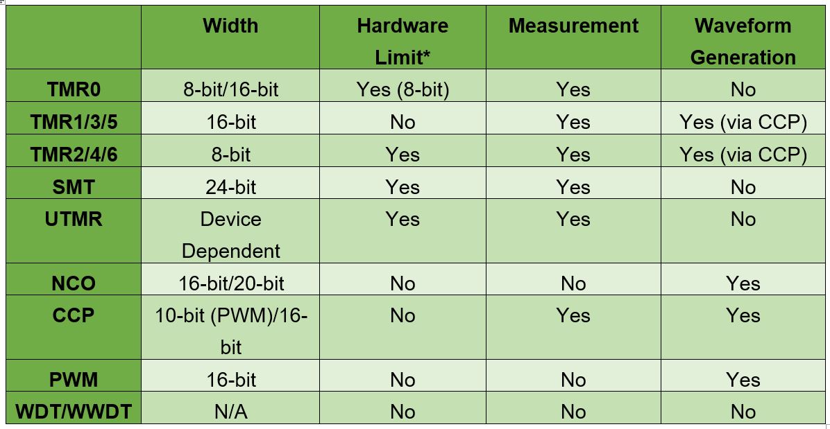
Timers are a ubiquitous peripheral in MCUs. It ought to come as no shock that there are quite a lot of timers, every with their very own use case that they excel at. Some timers are designed for use as a part of waveform era, whereas others are perfect for pulse counting. In lots of instances, there isn’t any improper selection—as an alternative, it should rely on the necessities and assets out there. For extra details about the timers, please see the linked peripheral pages within the desk under.
TMR0 can perform in 8-bit or 16-bit mode. When in 8-bit mode, the excessive and low byte of the timer are unbiased of one another. The timer rolls over when the worth set within the excessive byte matches the low byte. 16-bit mode is a free operating timer, the place the timer will rollover when it reaches the worth 0xFFFF. To stop knowledge corruption throughout learn/writes, the register is buffered, and solely latched on the low byte.
TMR1 is a 16-bit gated timer with assist for each synchronous and asynchronous clock alerts. When TMR1 is in asynchronous mode, the timer capabilities in sleep and might generate an interrupt to wake the microcontroller. The timer additionally accommodates a gating perform which can be utilized to carry the present worth. To stop corruption when studying/writing the 16-bit worth, the timer could be configured to buffer the counter. The information shall be latched on the low byte.
TMR2 is an 8-bit timer that helps one-shot and monostable modes of operation. One-shot mode triggers the timer, then clears the ON bit after reaching the {hardware} restrict. Monostable capabilities identically to the one-shot mode, besides that the ON bit stays set and the timer could be retriggered. TMR2 could be reset or triggered by an exterior sign.
The SMT is a big 24-bit timer that helps the next modes:
Be aware: Values in parentheses are different modes out there, e.g.: Windowed Counter, Gated Counter and Counter are all legitimate modes.
To assist these working modes, the SMT accommodates 4 24-bit registers. The precise conduct of the registers depends upon the mode.
The UTMR consists of two timer modules that may function independently of one another, or as one bigger timer. The scale of the UTMR might differ by system; at the moment on the PIC18-Q71 household, it’s 16-bit per module, or 32-bits if chained collectively. This timer was designed to include the functionalities of all legacy timers (TMR0, TMR1 and TMR2).
The UTMR helps each synchronous and non-synchronous clock sources and permits for studying the present depend with out stopping the timer, even with non-synchronous sources. To regulate the timer, there are three configurable occasions: Begin, Reset and Cease.
Begin occasions outline what begins the timer. The reset occasion defines what resets the depend again to zero. And there’s a cease occasion, which defines what is going to cease the timer utterly. These occasions could be at all times enabled, triggered from an enter sign or disabled fully. This permits options like monostable triggering, {hardware} limits and one-shot operation.
Be aware: The scale of the NCO (16-bits or 20-bits) might differ, relying on system household.
The NCO is designed to generate a periodic waveform by including a programmable increment to an amassed complete. When the full overflows, the overflow is stored, and a pulse is generated. The heart beat generally is a fastened variety of enter clock cycles in width, or it may be 50% output at the price of halving the output frequency. Whereas the NCO isn’t designed for measurement, it may be used if the NCO is stopped, learn after which restarted.
The CCP has three modes—Seize, Evaluate or Pulse Width Modulation (PWM). The Seize/Evaluate modes make the most of TMR1 whereas PWM makes use of TMR2.
The Seize mode shops the worth in TMR1 when a rising or falling occasion happens (relying on working mode). The Evaluate mode generates an output when the worth in TMR1 matches the set worth within the CCP. For PWM mode, TMR2 is 8-bit, however the CCP extends it to 10-bit utilizing the inner oscillator’s prescaler bits.
Be aware: For PWM that depends upon TMR2, see the CCP part.
The 16-bit PWM peripheral is absolutely standalone—which means that it doesn’t make the most of one other system timer, in contrast to CCP (which depends upon TMR2). There are 5 working modes for producing PWM:
These modes change how the depend is used to generate the output. Inside of every occasion are slices, every containing two outputs. The outputs share a standard frequency however have their very own responsibility cycle registers. Moreover, the peripheral is double buffered for clean output adjustments and could be synchronized with different PWM situations.
The WWDT is a particular timer designed to detect a impasse within the microcontroller. A WWDT is a timer that runs the background. Periodically, software program should clear it via a particular sequence, or it should reset the microcontroller. WDT and WWDT differ solely in that the WWDT has a “Window” function. The “Window” function can require the clearing sequence to be carried out inside a sure time window, quite than any time earlier than the timer rolls over. This prevents a impasse from being undetected by clearing the timer constantly.
After understanding the timer peripherals, choose which timer closest matches the options wanted within the utility. In lots of instances, there are a number of doable timers that may carry out the duty. On this case, choose the best timer—this leaves timers with extra capabilities out there for future use. The system datasheet, utility notes and technical briefs go into extra element on how all of those timers function and the registers related to them. Code examples that use a selected timer could be discovered by looking out MPLAB Uncover.
POCO continues to make one of the best funds telephones, and the producer is doing…
- Commercial - Designed for players and creators alike, the ROG Astral sequence combines excellent…
Good garments, also referred to as e-textiles or wearable expertise, are clothes embedded with sensors,…
Completely satisfied Halloween! Have fun with us be studying about a number of spooky science…
Digital potentiometers (“Dpots”) are a various and helpful class of digital/analog elements with as much…
Keysight Applied sciences pronounces the enlargement of its Novus portfolio with the Novus mini automotive,…